
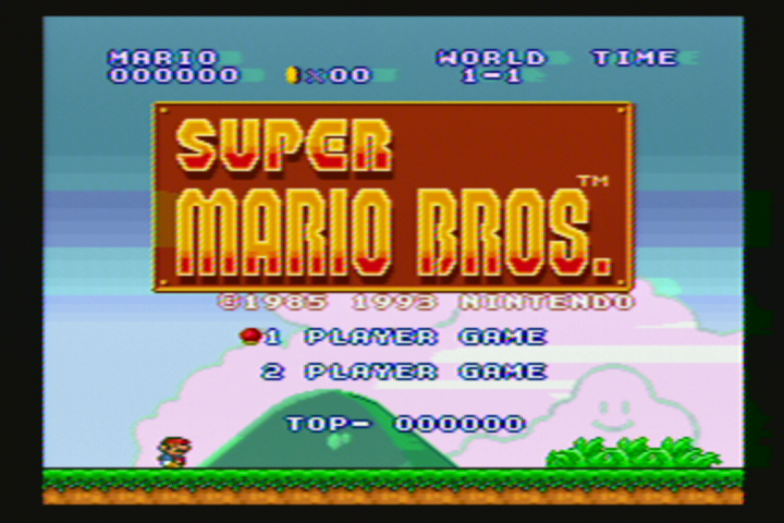
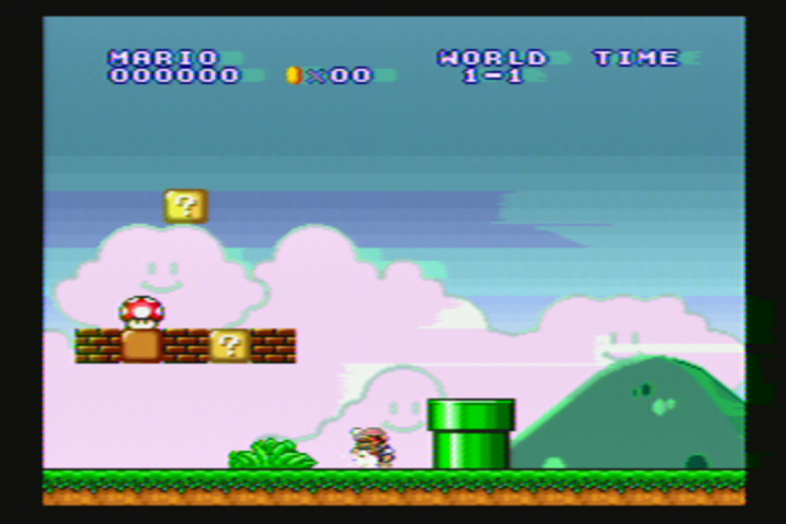
It's always best to test a console for proper function before modding or painting it. Unfortunately, I did not test my Super Nintendo (SNES) prior to painting it. It had been in storage for years, and I assumed that it would work just as well as it did before placed into storage. When I reassembled the console and put in Super Mario All-Stars, I was greeted with some graphical issues.


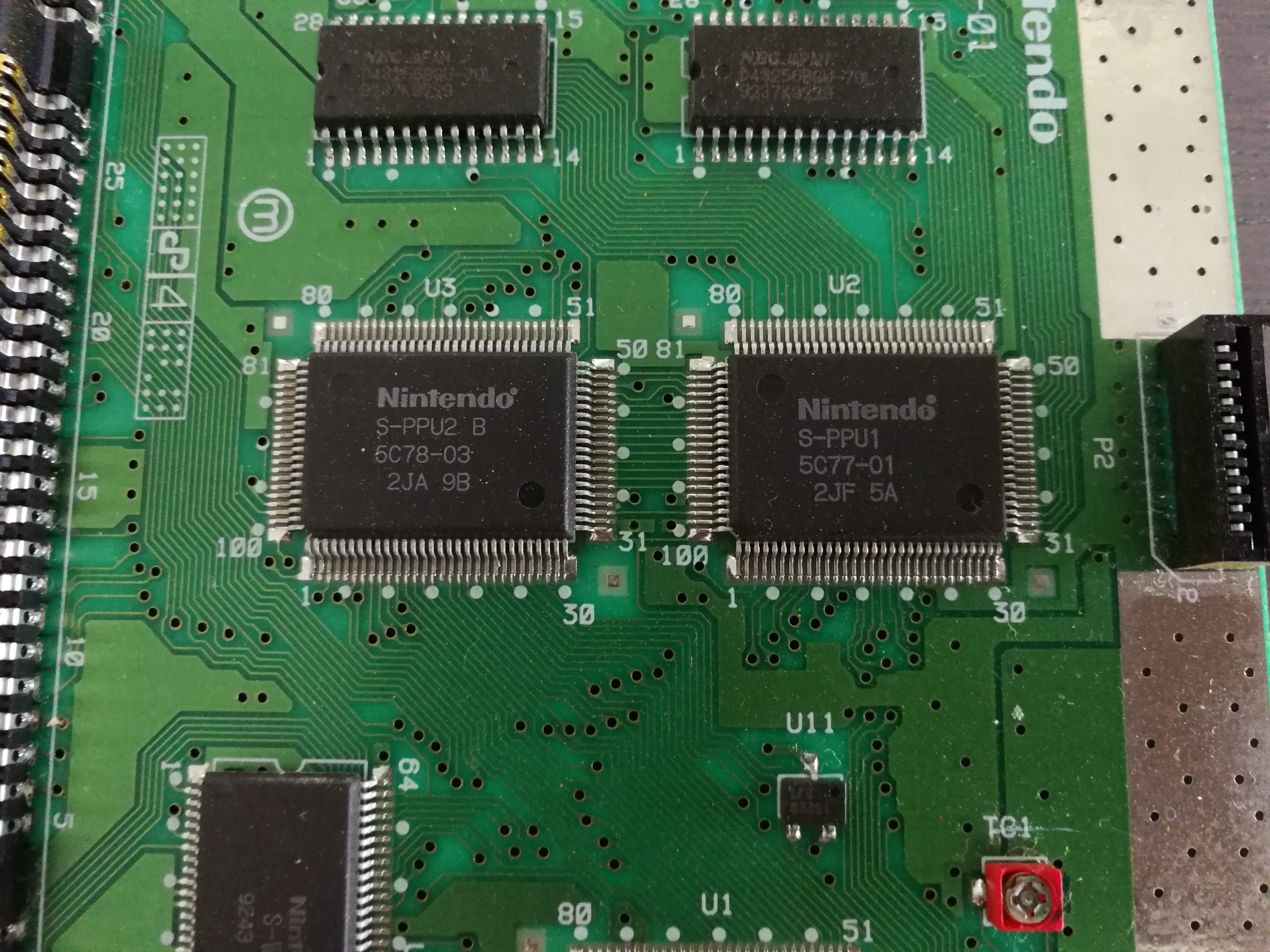
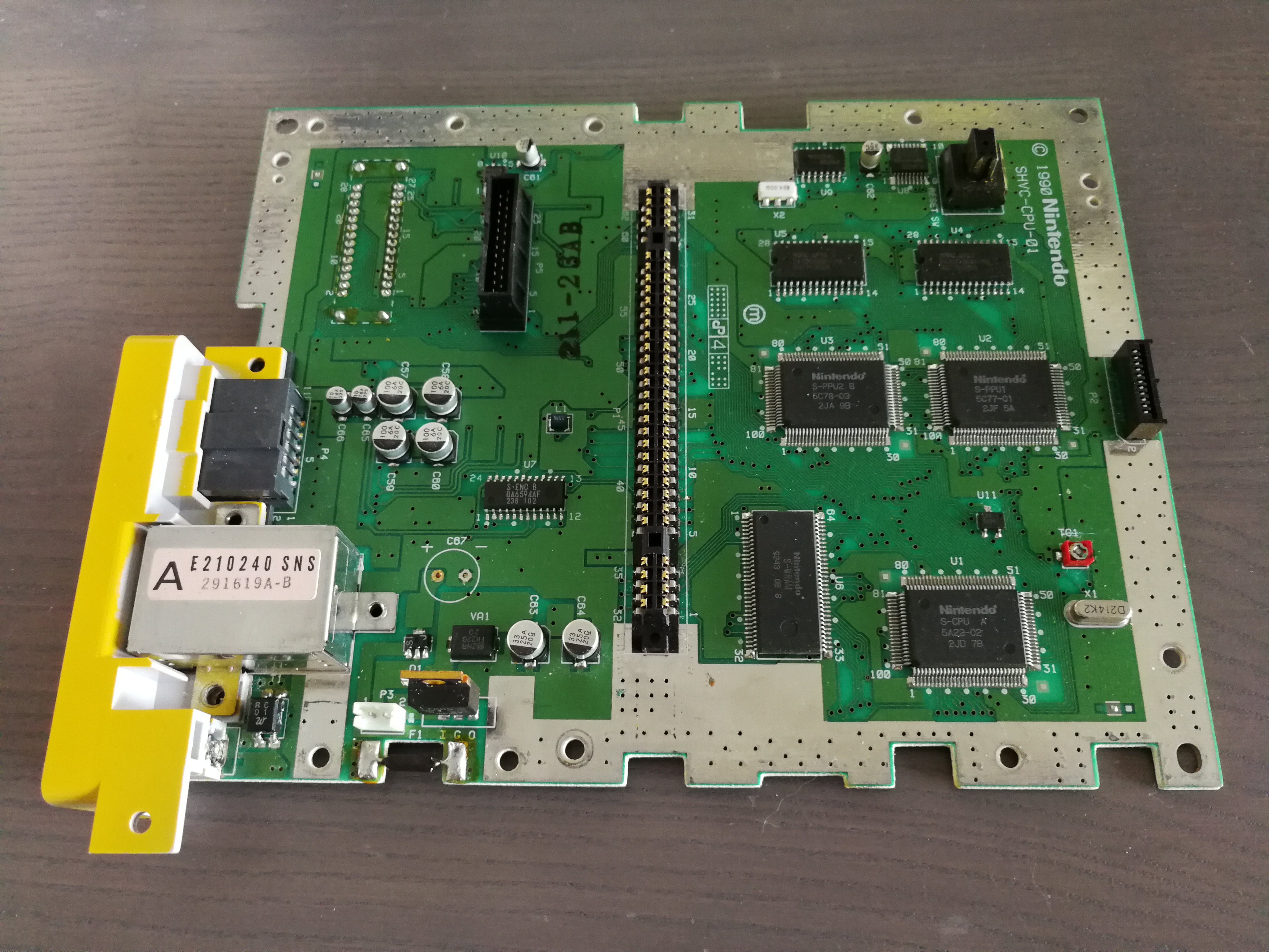
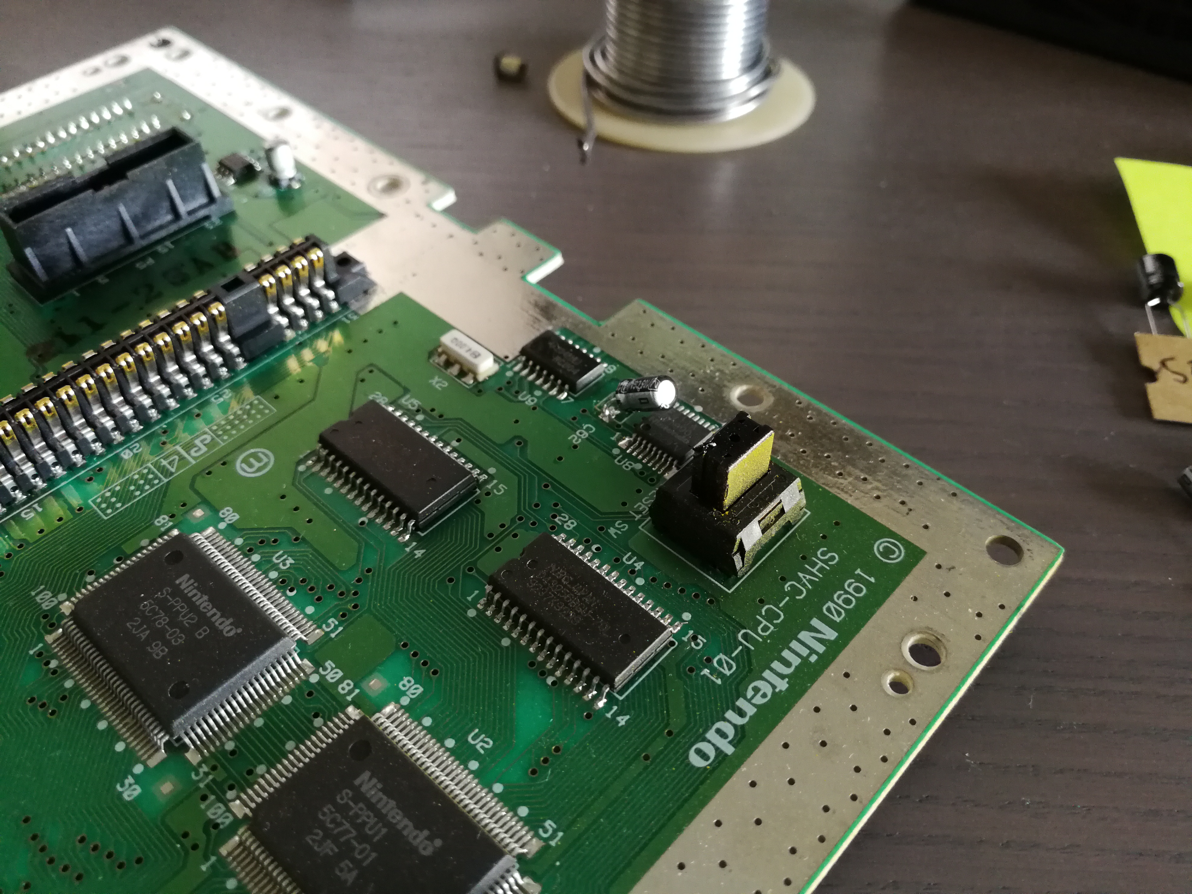
It seems that many of the first-generation SNES units have been having issues with failing PPU (Picture Processing Unit) chips lately. On my first-generation console (model SHVC-CPU-01), there are two PPU chips. If they are failing there is no cure for it and it will progressively get worse.
However, it is also possible that this is merely an issue with failing capacitors, which are a common issue on most any aging piece of electronics. Capacitors can be replaced, and if they were the cause of the problem it will be back to working perfectly. At this point, my system could have either issue. Since capacitors are cheap, and soldering is a skill I have, it's worth trying to replace them to fix these graphical issues.
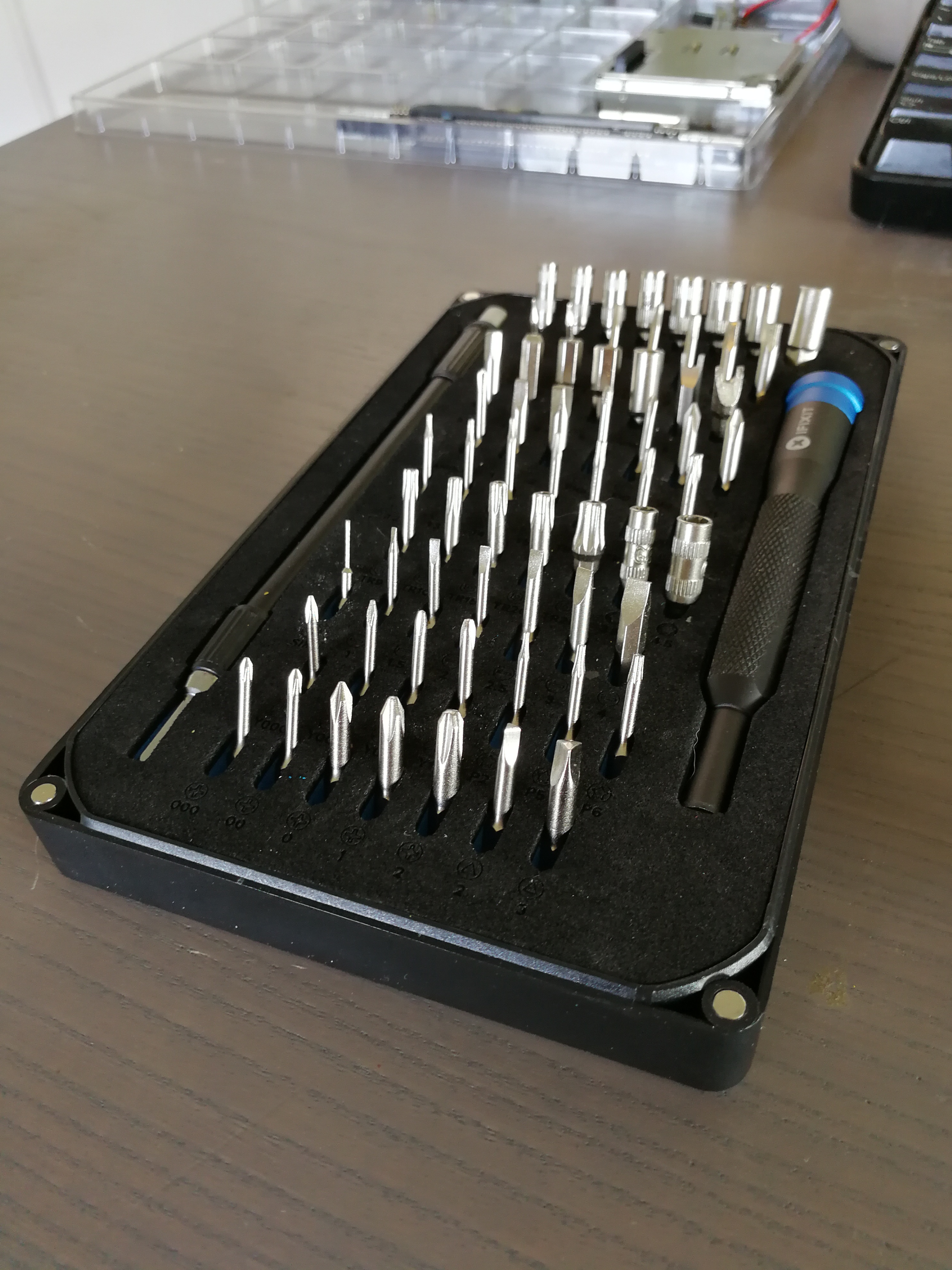
The first step is to acquire the needed tools and parts. The outer shell of the SNES is sealed with Nintendo's security screws, so a bit driver with the appropriately sized security bit is needed to remove the case. Once inside, only common phillips-head screws are used.
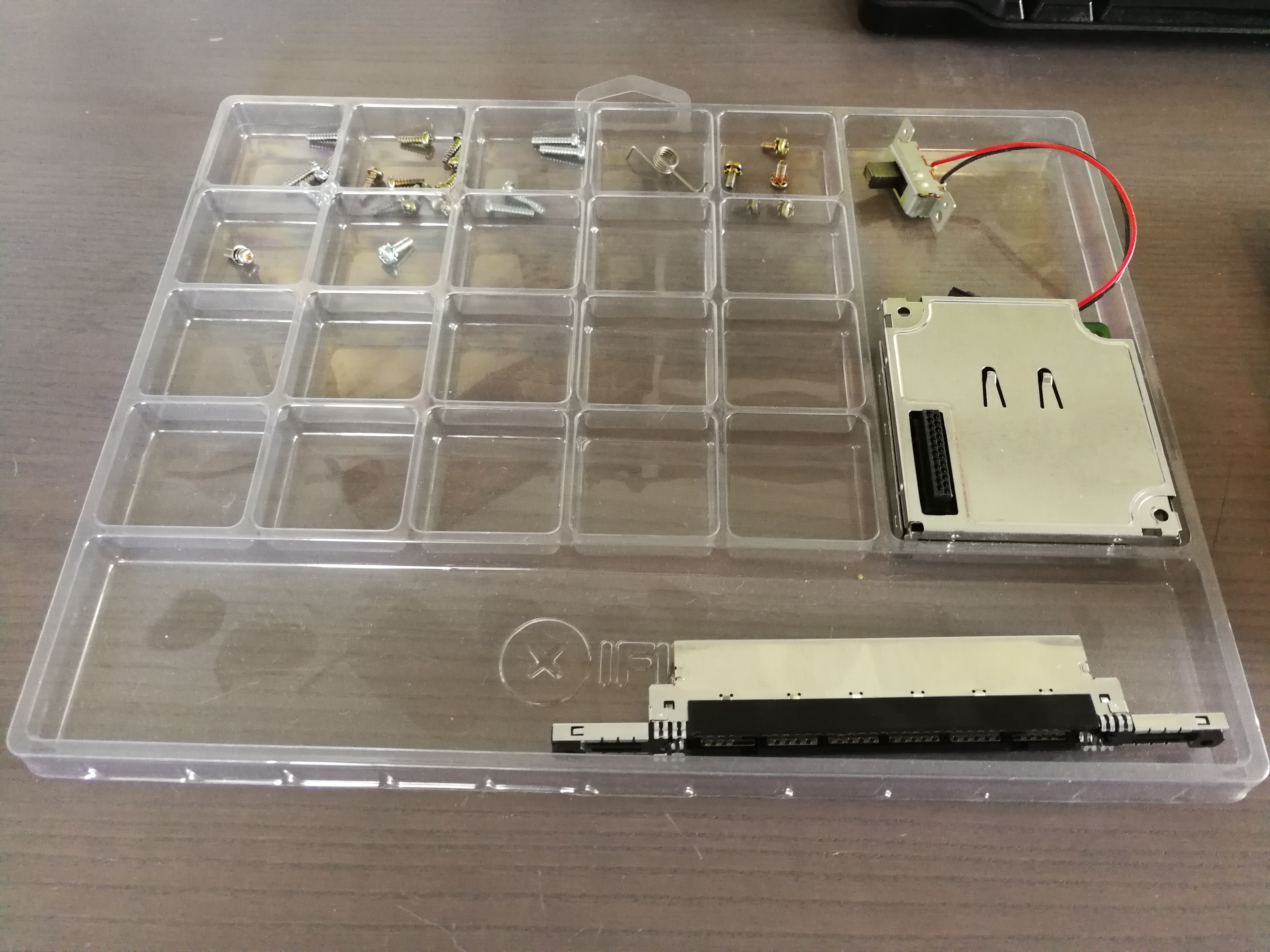
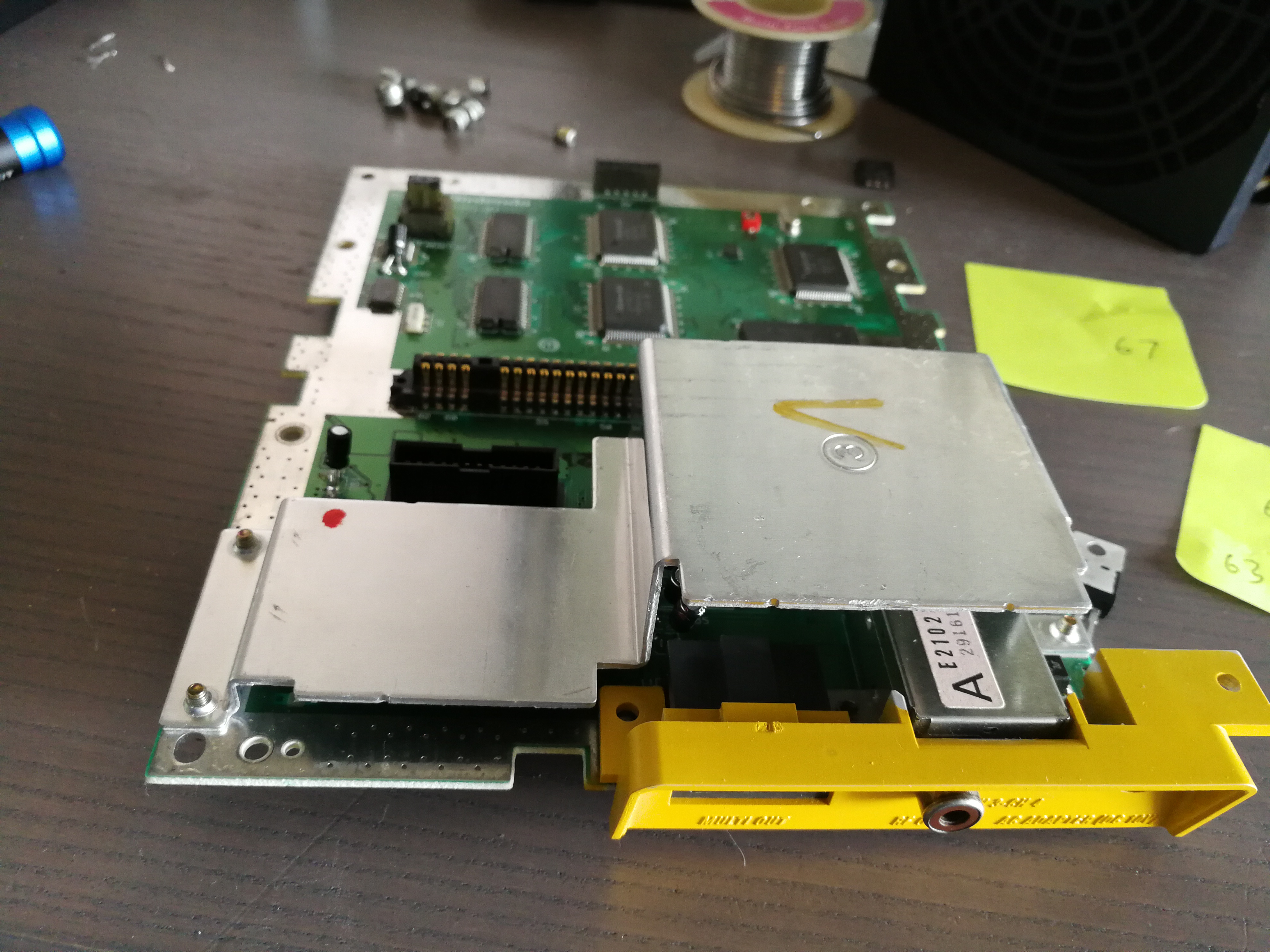
A parts organizer is helpful, as there are at least four or five different sizes of screws and it could be tricky to keep them from either getting lost or mixed up. Additionally, an audio processing unit (APU) and the cartridge slot are both removable, and this particular organizer from iFixit seems to hold those just fine.
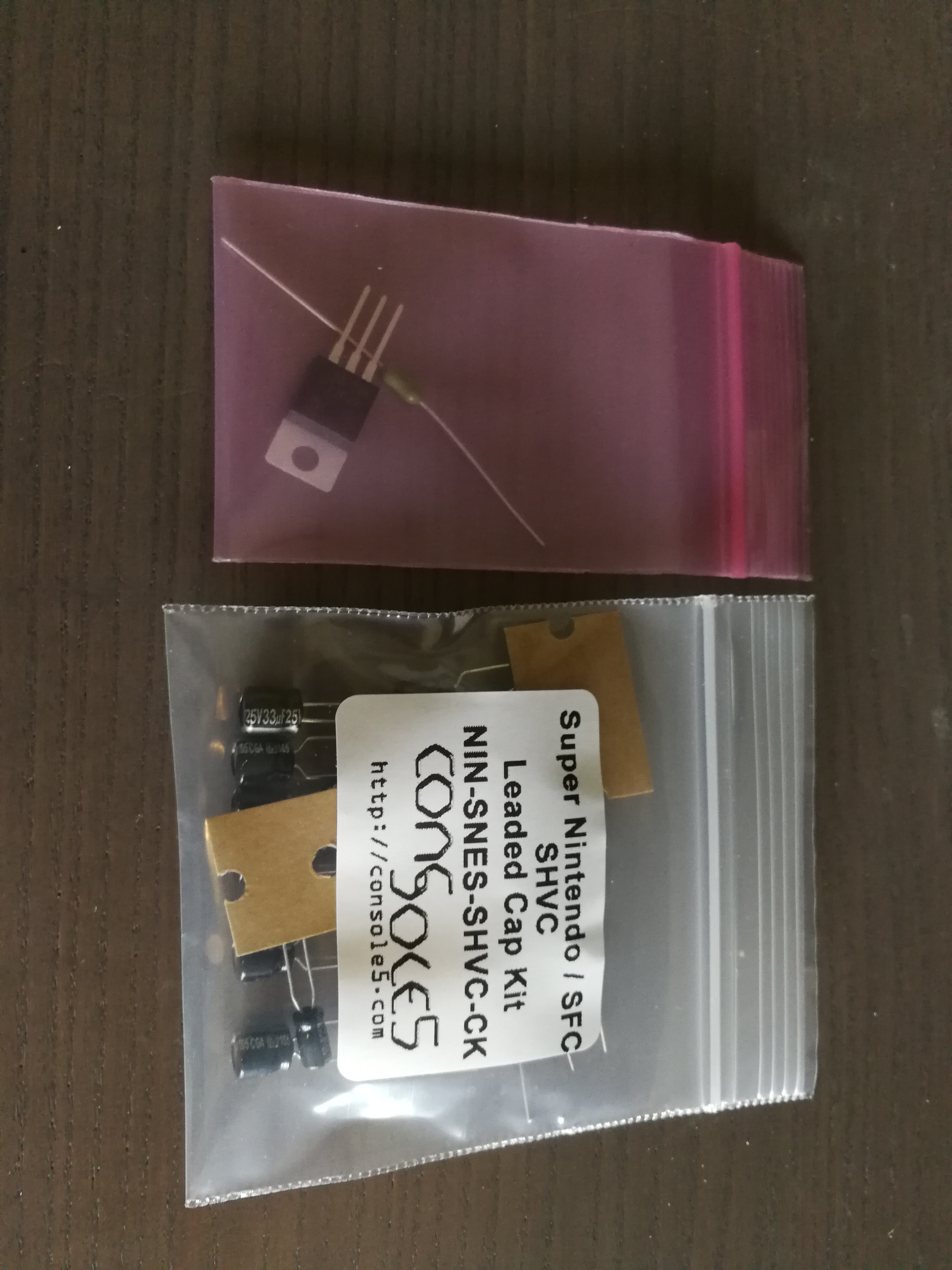
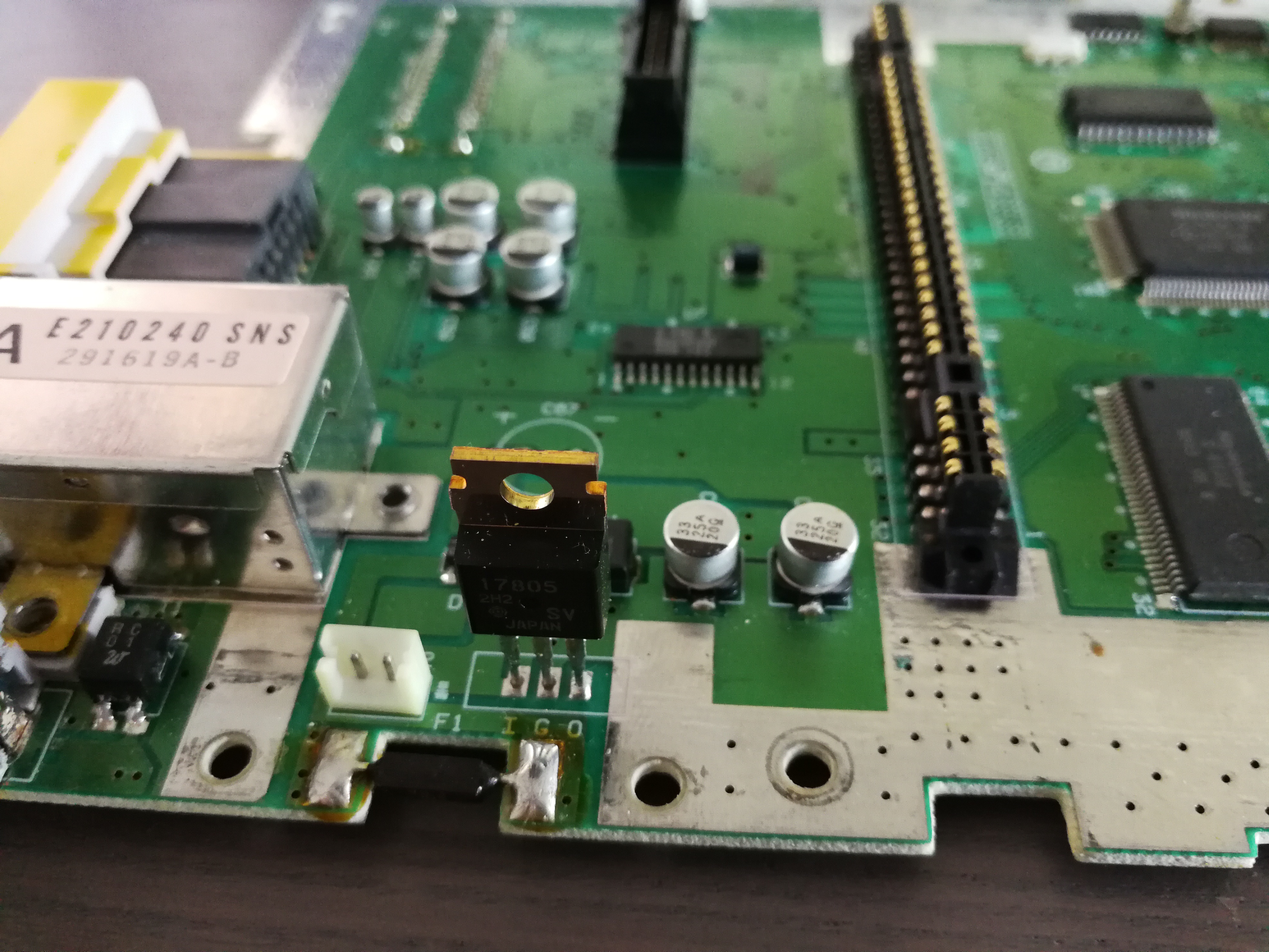
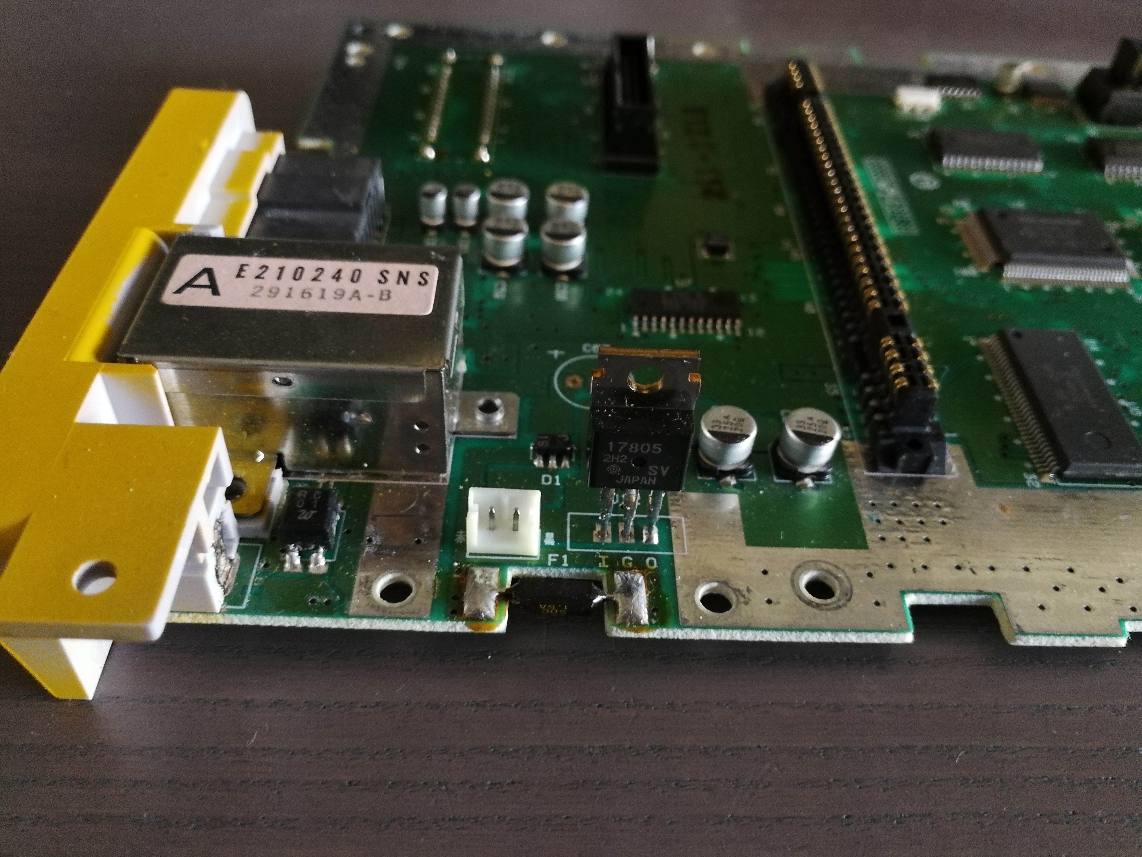
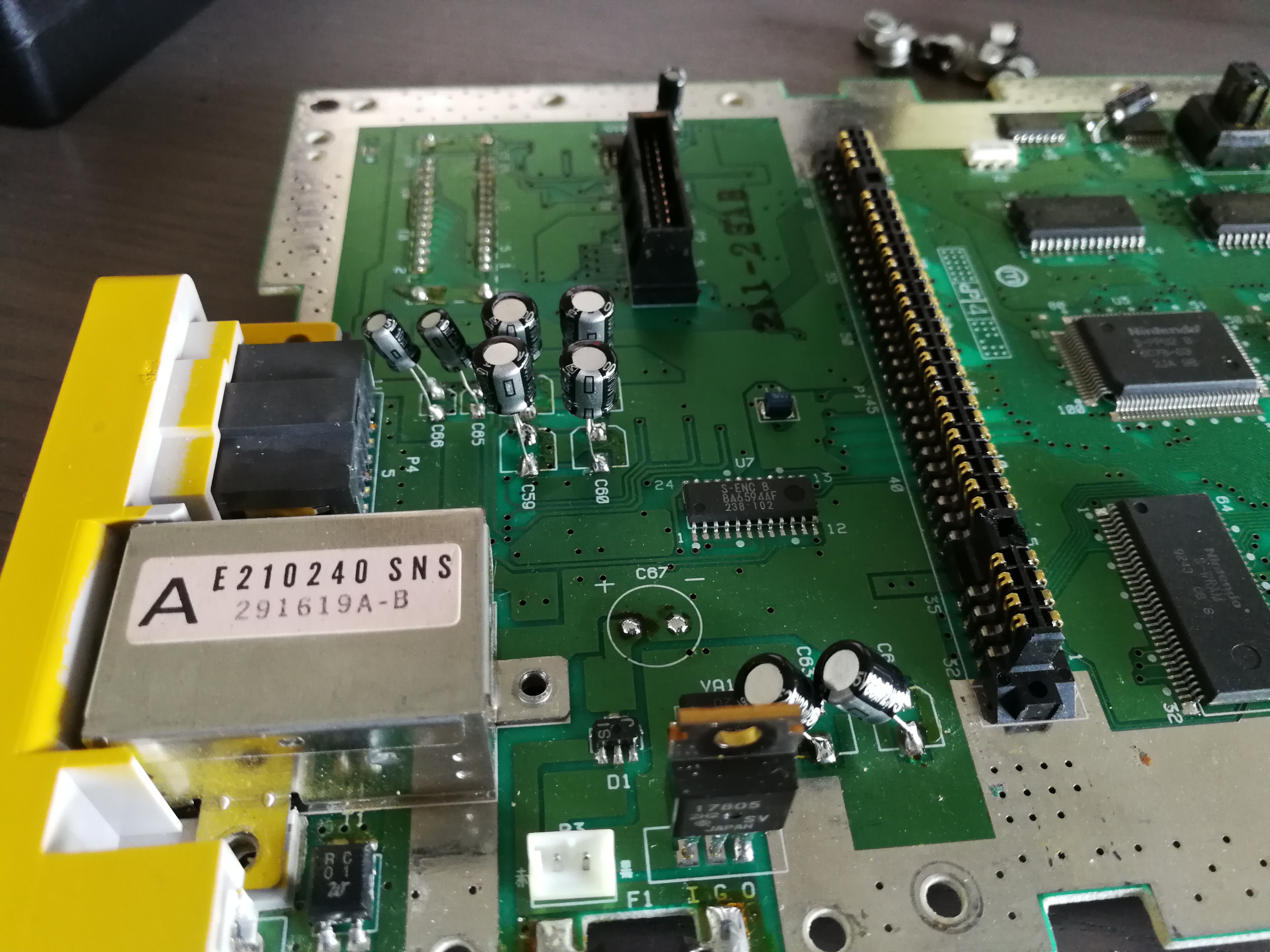
I purchased a capacitor kit from Console5, which includes all capacitors for this model SHVC-CPU-01 board and the APU. Because some are so similar in size, I cross-referenced them each to the marked location on the board that they will need to be soldered to. I bought a replacement voltage regulator and fuse for the board as well.
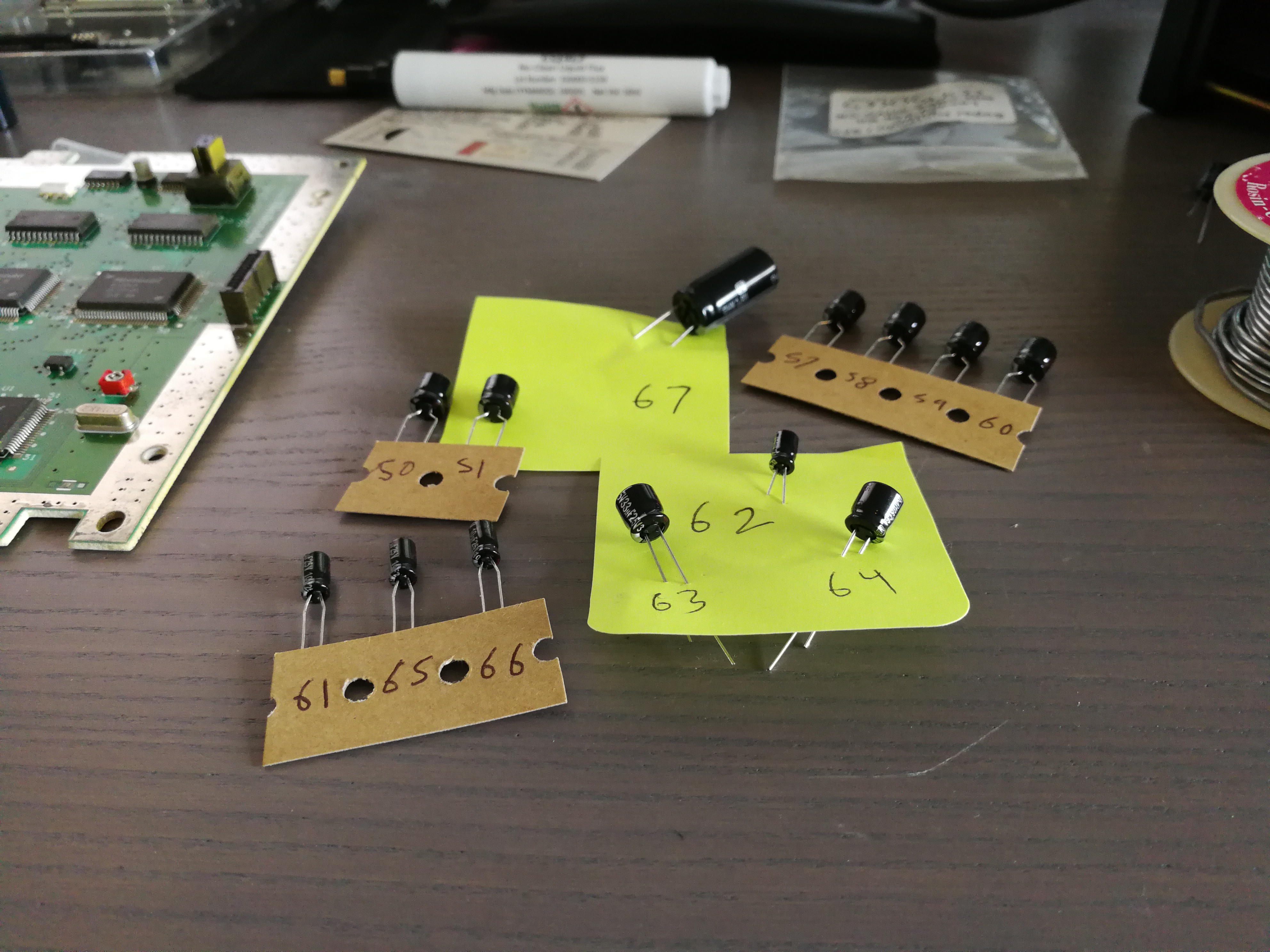
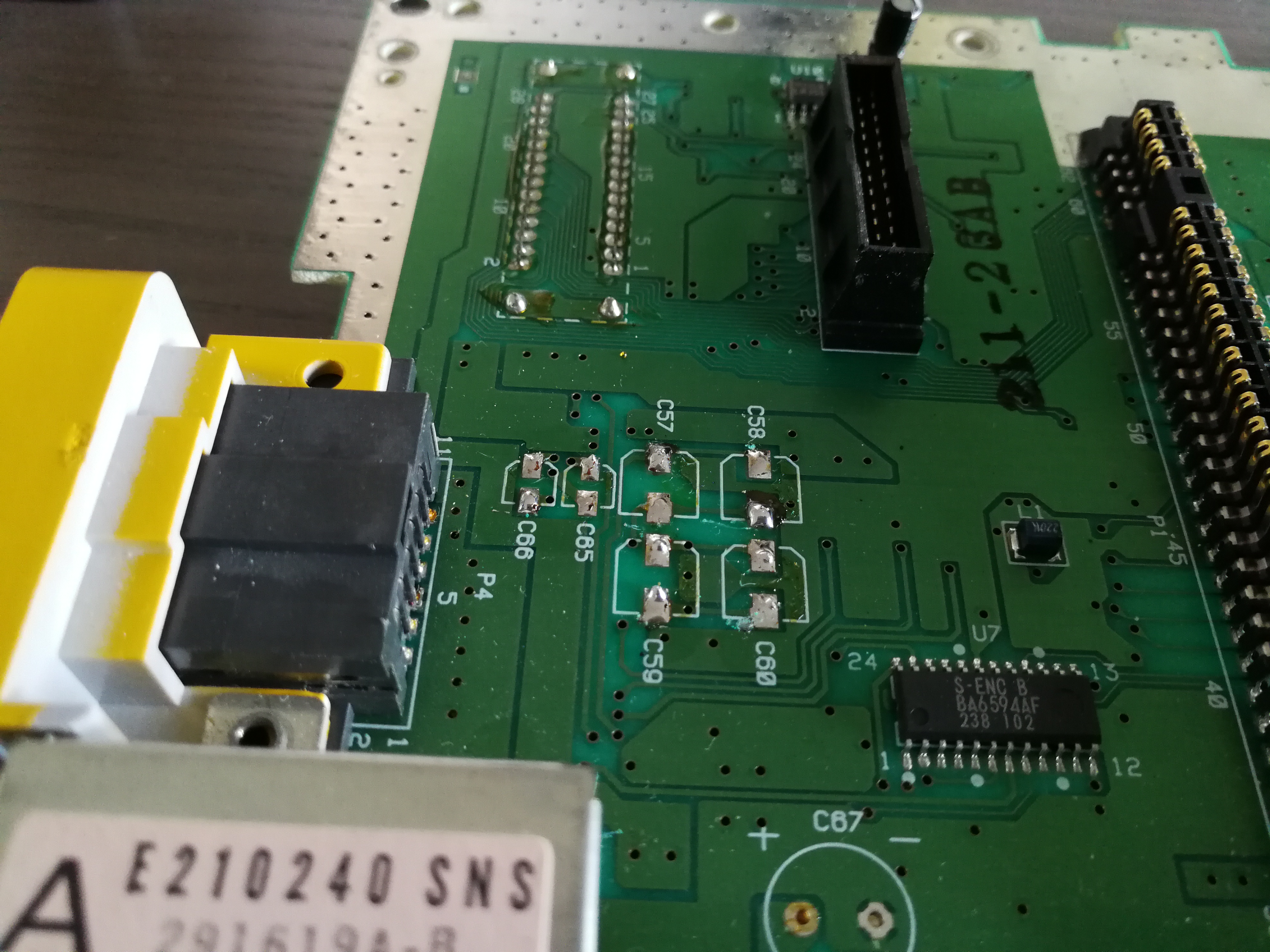
The capacitors on the SNES mainboard are all surface mount. Console5 offers both capacitors with leads or as surface mount components. I prefer working with leaded capacitors, so I will be trimming the leads and soldering them to the same solder pads. It does not matter which type of component is used.
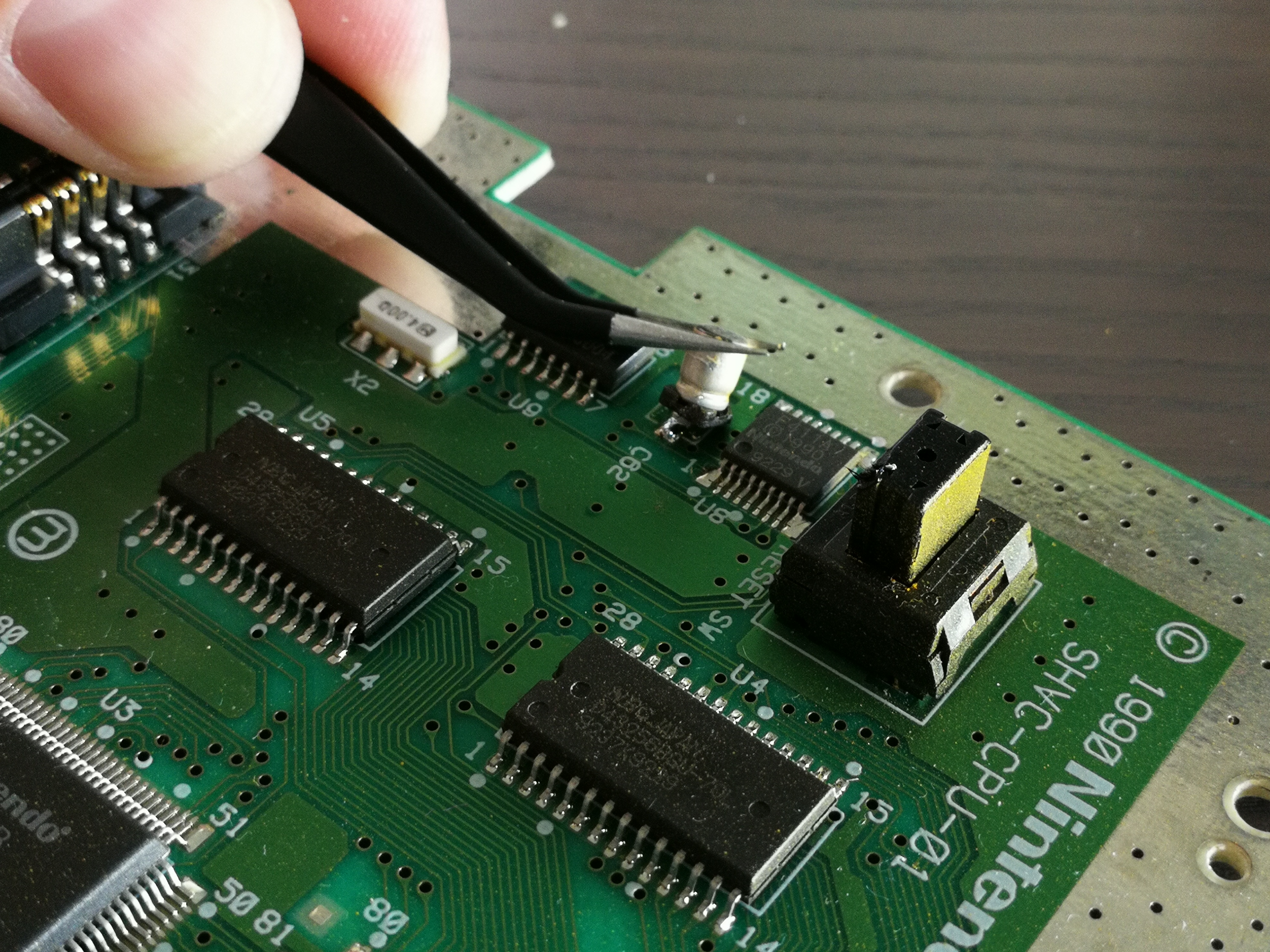
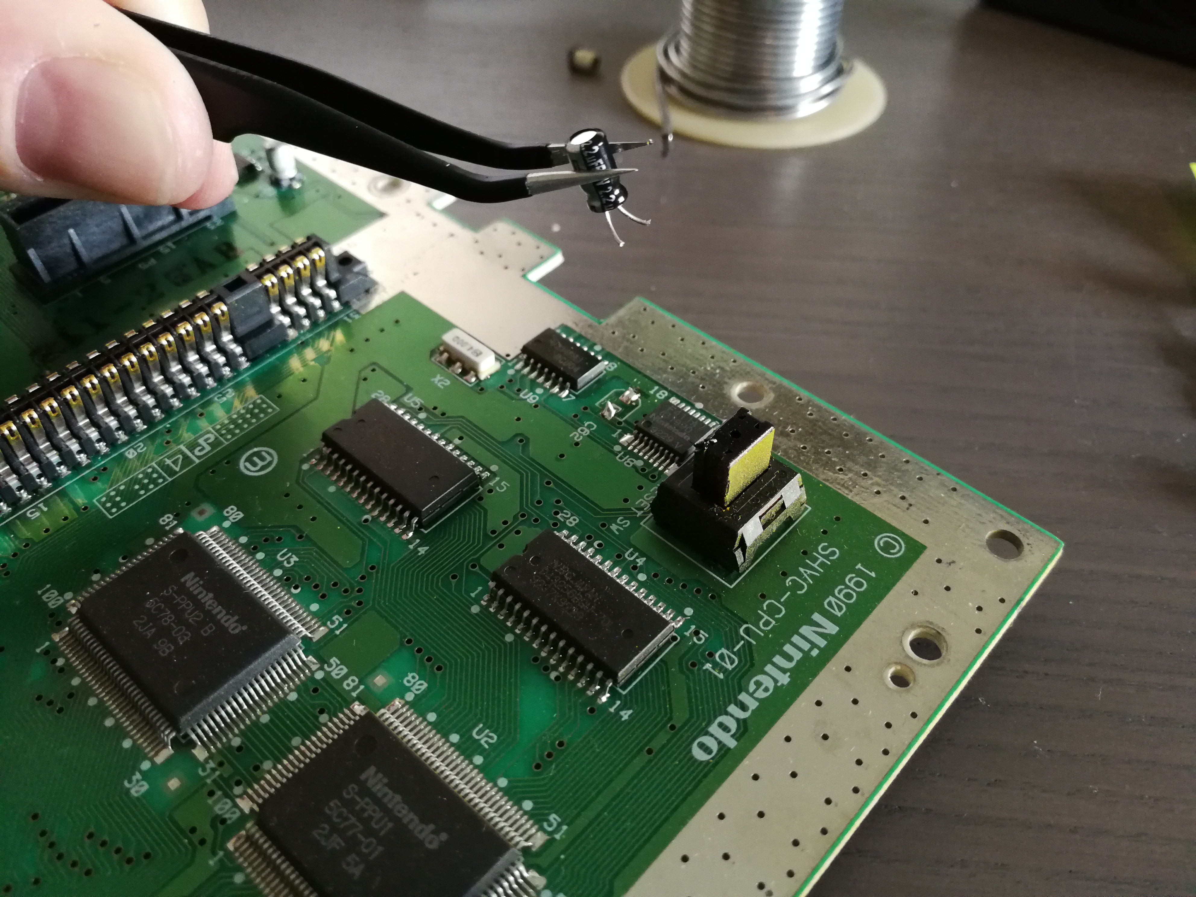
To remove a surface mount capacitor, heat up one side's solder pad and tilt the capacitor away from it. Repeat for the other side and it should come right off. Do not forceably pull them off. If they don't seem loose enough after heating both sides, keep heating and tilting. If you try to pull them off you may remove the solder pad too.
Trim the leads off of the new capacitor, short enough that it will sit close to the board. Tin the solder pads with fresh solder, then solder each lead to the appropriate pad. You must solder them in the proper polarity. If you do not, you are either going to blow the fuse or you are making a series of small bombs.
As mentioned, tinning (placing more solder on the pads) is helpful for preparing to attach the new components.
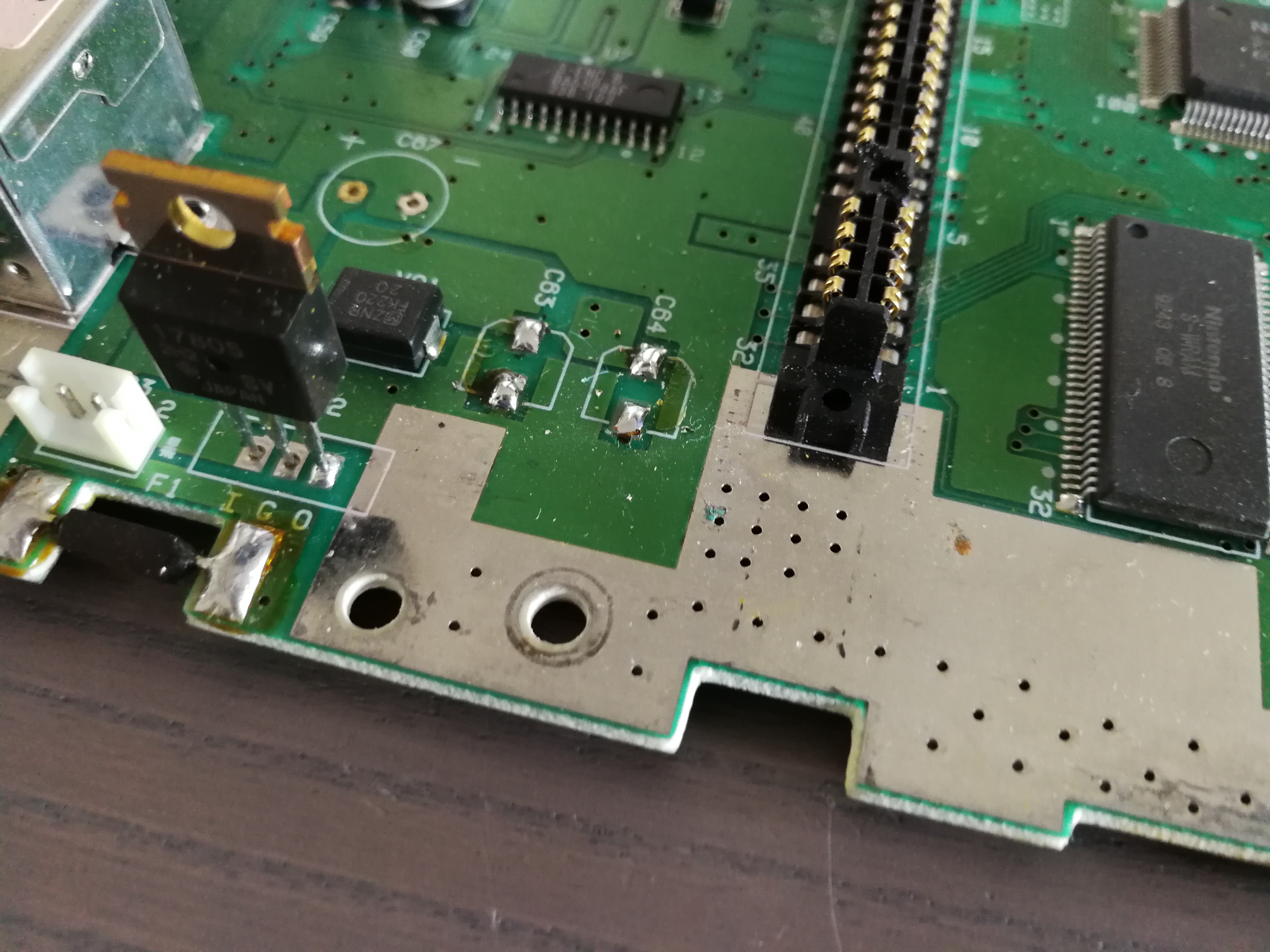
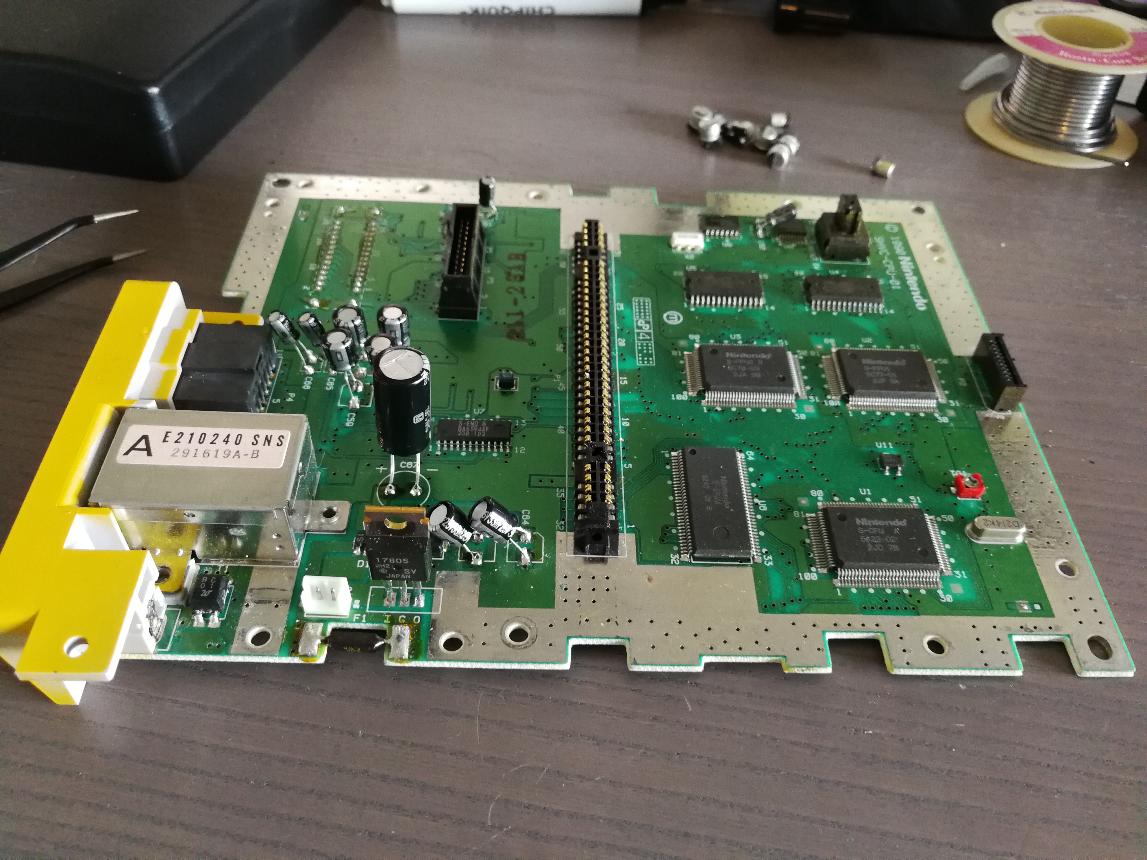
It's helpful in this area to remove all the capacitors before trying to solder in new ones. The position marked C67 is for a capacitor which was not originally present on this board. Instead, it was moved to the power supply as a filter. Since it does no harm to install the capacitor from my kit here, I'll be doing so. It's the largest of the bunch.
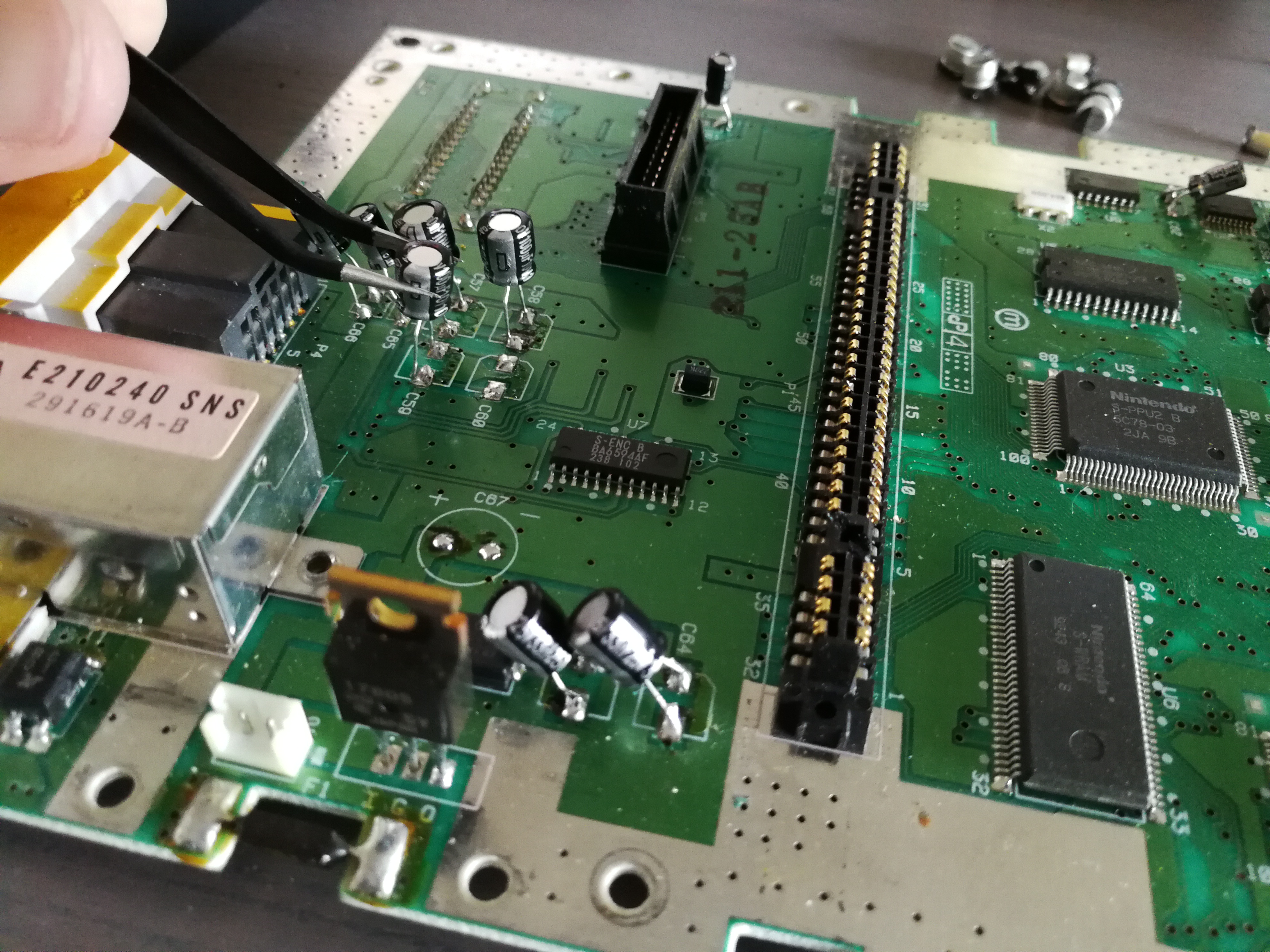
All capacitors are installed!
Well...did it work? Was this the issue all along? Part 3 will reveal the results of this project...